Beginners Electron Beam Welding Guide
Electron Beam Welding Guide
The purpose of this Electron Beam Welding Guide document is to provide engineers not familiar with electron beam welding a basic understanding of the process.
Contents
- What is electron beam welding?
- Applications and Materials
- Joint designs
- Inspection Techniques
- Design considerations
What is Electron Beam Welding?
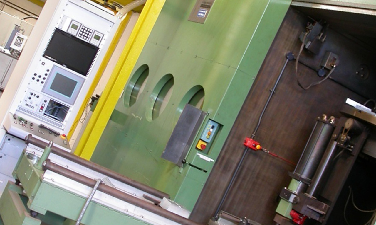
Electron beam welding is the bombardment of a metallic surface by a tightly focussed stream of electrons. This results in a very concentrated (approx. 0.1mm dia.) and intense heat source that melts the metal. By aiming the beam at a joint and then moving the joint under the beam a fully homogeneous fusion of the mating surfaces can be achieved. This activity is carried out within a vacuum chamber thus preventing the beam from being defused by air molecules and also providing a virtually inert atmosphere.
When the beam hits the joint it creates a ‘keyhole’ in the material that is surrounded by a molten sleeve of parent metal. As the work traverses under the beam this molten sleeve solidifies and creates the joint. The resultant welded joint is in affect a vacuum re-melted area of parent material.
Applications
The use of electron beam welding can be found in virtually every market; aerospace, medical, automotive, nuclear, defence, oil and gas, civil engineering and even art.
Assemblies can be welded using finished or part finished details using a vast range of materials. The most common are; titanium, stainless steel, Inconel, aluminium, copper, low carbon steel, bronze, super duplex, hastalloy and magnesium.
Benefits
Electron beam welding is particularly effective when fusing delicate assemblies where excessive heat could be detrimental to the product. It can also be an economic alternative to conventional welding techniques when joining deep sections, as a single pass with an E.B. weld can replace multiple runs using TIG, MIG or Arc methods.
Further advantages are; minimal distortion, a very narrow HAZ (heat affected zone) and as the welding normally takes place within a vacuum environment the risk of hydrogen contamination of the weld is minimised. This is a great advantage when fusing titanium and its alloys.
Joint Designs
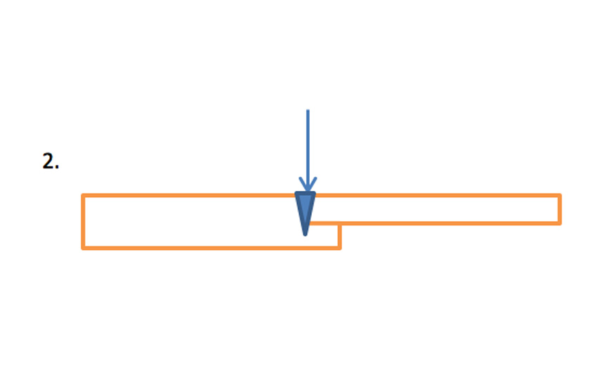
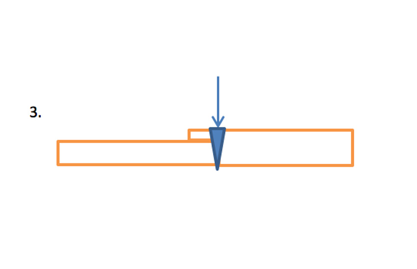
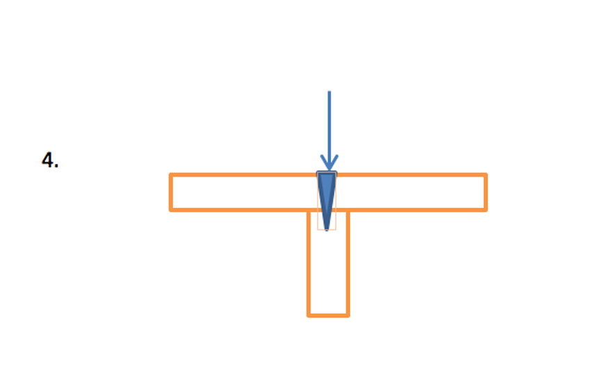
Following is a range of different joint designs that are acceptable for electron beam welding. A fully penetrating weld as shown in figure 1 is often used when the assembly requires no post weld machining. Figures 2 & 4 show joint designs that provide location for the mating parts which makes assembly simpler. This type of configuration can also lend itself to finish machined details though the additional material used to locate the joint is sometimes removed after welding. Figure 3 is a joint that although fully penetrating will probably require the top joint feature to be removed after welding. This is will prevent crack propagation from the unfused section of the joint.
Inspection Techniques
Most standard NDT techniques can be used to check the integrity of electron beam welds; x-ray, PFD, ultrasonic and MFD.
Design Considerations
Are the selected materials suitable for electron beam welding?
See list in section 2
Can the joint be accessed by a beam of electrons?
Ensure nothing can eclipse the path of the beam.
Can the joint be designed as self-locating or will a fixture be required?
The joint tolerances must provide a maximum gap of 0,1mm. It some cases this may need to be even tighter. Consider the proximity of components that might be affected by temperature.
Will the design incorporate finish sized details or parts that require post weld machining?
If finished parts are to be welded the amount of weld shrinkage will need to be considered. Most materials will lose some of their mechanical properties after welding so an assessment of strength requirements will need to be made.


